
The Urban Heat Paradox
Modern air conditioning solves an immediate human problem: it keeps apartments, offices, hospitals, shops, and data centers within a tolerable temperature range. Yet in dense districts, that comfort can intensify the conditions outside. Every conventional air-conditioning system must move heat somewhere. A window unit, rooftop package unit, or air-cooled chiller extracts heat from an interior space and discharges it into the surrounding air. When hundreds or thousands of buildings perform that same exchange at once, street canyons become the receiving basin for a vast amount of thermal energy.
The result is a troubling urban feedback loop. Dark roofs and pavement absorb solar radiation, tall buildings restrict airflow, and mechanical equipment adds more heat at precisely the time when outdoor temperatures are already stressing people and electrical grids. According to the US EPA guidance on reducing heat islands, urban surfaces and infrastructure can raise energy costs, worsen air pollution, and increase heat-related health risks. Subterranean district cooling offers a different municipal logic: instead of asking every building to reject heat independently into the same crowded airspace, a shared network concentrates cooling production and directs unwanted heat toward water, ground, storage, or other suitable thermal sinks. The shift may begin with one plant and a few connected buildings, but the benefits can grow from block to borough.
How Traditional Chillers Trap Heat in Urban Canyons
Individual cooling systems rely on a vapor-compression cycle. A refrigerant absorbs heat from indoor air or from chilled water, is compressed to a higher pressure and temperature, and then releases that heat through a condenser. In an air-cooled system, fans push outdoor air across condenser coils. The warmed air leaves through rooftop exhaust fans or the rear of a packaged unit. Water-cooled systems can be more efficient at large scale because condenser water carries heat to a cooling tower, but the tower still commonly releases that energy into the atmosphere through evaporation and airflow.
At building level, this process is physically straightforward but spatially consequential. Equipment mounted on roofs and façades produces warm exhaust plumes, fan noise, vibration, and maintenance demands. Between high-rises, wind may be weak or redirected upward, allowing heat to linger near pedestrian level. A hotter outdoor environment then raises the condensing temperature of air-cooled equipment, forcing compressors to work harder. The same buildings that are adding heat are therefore operating under less favorable conditions, increasing electricity use during peak demand periods.
Decentralized equipment also fragments investment and operations. A district may contain hundreds of compressors, pumps, control systems, refrigerant circuits, and replacement schedules. A central plant can aggregate diverse loads, use larger and more efficient equipment, include thermal storage, and connect to multiple energy sources. That does not make district cooling automatically superior in every location. Network construction requires major capital, suitable density, coordinated ownership, and long-term planning. The comparison is best understood as a trade-off between scattered simplicity and shared efficiency.
| Cooling approach | Where heat is rejected | Urban implications |
|---|---|---|
| Window and split systems | Directly to outdoor air | Fast installation, but many exhaust points, compressors, and noise sources |
| Rooftop packaged units | Through rooftop condenser fans | Independent control, but cumulative roof heat and maintenance complexity |
| Central building chiller | Air-cooled coils or cooling tower | More efficient at building scale, while still concentrating heat on one property |
| District chilled-water network | Lake, river, geothermal source, storage, or central heat-rejection equipment | Shared capacity, fewer street-level exhaust points, and potential for phased expansion |
The Subterranean Loop Anatomy
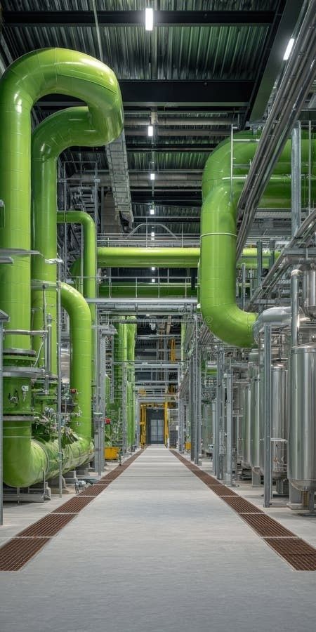
A district cooling network has three essential layers: a central production plant, insulated distribution mains, and building-level energy transfer stations. The plant produces chilled water using chillers, heat exchangers, pumps, and controls. Underground supply and return pipes carry that water through public rights-of-way. At each connected building, a heat exchanger transfers cooling into the building”s own air-handling or fan-coil system without requiring the district water to circulate through occupied spaces.
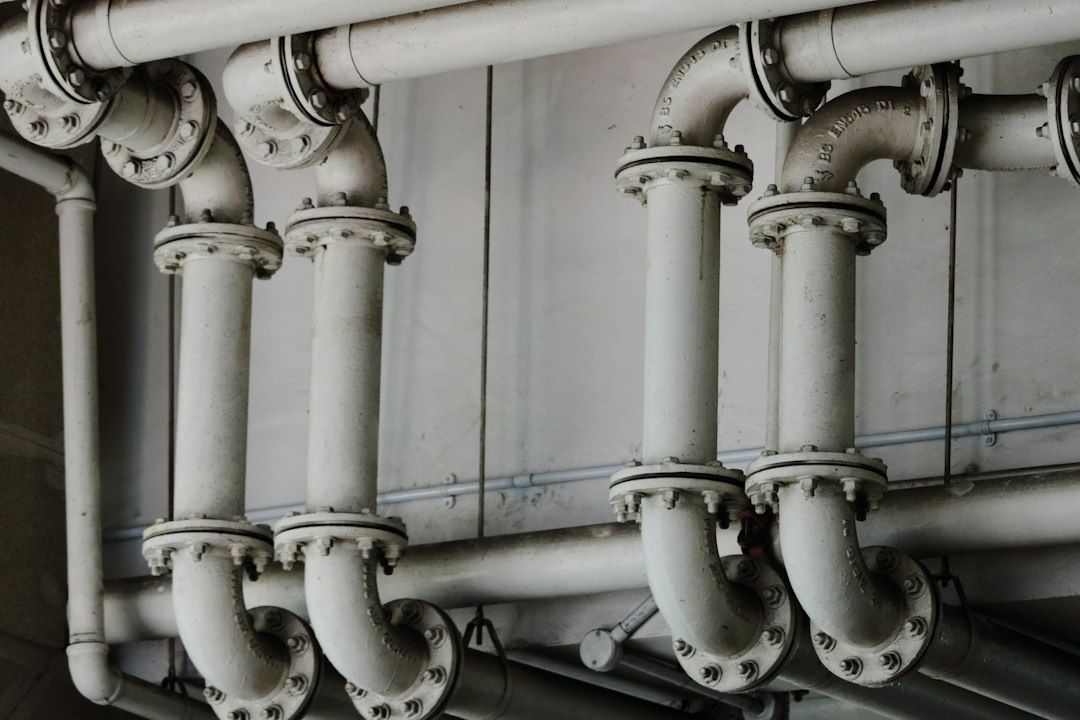
Many chilled-water systems operate with supply water near 40 degrees Fahrenheit, or approximately 4 to 6 degrees Celsius, depending on design conditions. After absorbing heat from building air, the water returns warmer, often near 54 degrees Fahrenheit, or approximately 12 degrees Celsius, before being cooled again. The loop is closed, so the same treated water can circulate repeatedly. The network itself does not eliminate heat. Its value lies in controlling where heat is collected, how efficiently it is moved, and which thermal sink receives it.
- Heat enters the building system. Warm indoor air passes over cooling coils, where heat transfers into chilled water returning through the building”s internal loop.
- The transfer station separates systems. A heat exchanger passes thermal energy from the building loop to the district loop while maintaining hydraulic separation between properties.
- The central plant restores cooling capacity. Chillers or other heat-exchange equipment remove heat from the returning district water and send colder water back into the supply main.
- The thermal sink receives the rejected energy. Depending on local conditions, heat may move into deep lake water, a river, geothermal formations, cooling towers, thermal storage, or a combination of sources.
- Controls balance the network. Pumps, valves, temperature sensors, and building meters adjust flow so the system responds to changing occupancy, weather, and demand.
This arrangement also creates an important planning advantage. A building does not need to reserve its roof for a large chiller array or cooling tower, and replacement work can be concentrated at the plant rather than repeated across every property. However, insulation quality and pipe condition remain critical. Heat gain in underground mains, water leakage, corrosion, and poorly calibrated controls can erode expected performance. District cooling is infrastructure, not a set-and-forget appliance, so long-term asset management must be built into the business model from the beginning.
Tapping Natural Heat Sinks for Municipal Scale Relief
Water is often a powerful thermal resource because large bodies of water can remain substantially cooler below the sun-warmed surface. Toronto”s deep lake water cooling system illustrates the potential. The project draws approximately 70,000 gallons per minute of water at about 39 degrees Fahrenheit from Lake Ontario through three 63-inch-diameter high-density polyethylene pipes extending roughly 18,000 feet to a depth of 280 feet. That cold lake water cools the circulating chilled-water system before being routed into Toronto”s potable water distribution system. According to the project description, the system reduces electricity use by approximately 90,000 megawatt hours annually while also lowering water consumption and operating costs.
Other cities are using different local conditions. District cooling projects in Europe draw on seawater, rivers, geothermal wells, recovered heat, and integrated heating and cooling networks. The appropriate source depends on water quality, environmental permits, geology, seasonal temperatures, distance from the load, and the safeguards required during drought or extreme weather. A natural heat sink is not a free resource. Intake structures, filtration, pumps, monitoring, and ecological protections all require careful design and ongoing oversight.
- Deep water systems can provide relatively stable low temperatures and reduce compressor work, particularly where a dense load lies near a deep lake or sea.
- Geothermal systems can exchange heat with the ground, although drilling conditions, land availability, permitting, and aquifer protection determine feasibility.
- Recovered heat and thermal storage can link cooling with wider district energy planning, shifting loads away from peak electricity periods.
- Centralized heat rejection can remove many rooftop cooling towers and condenser fans from individual buildings, freeing roof space for solar panels, green roofs, public terraces, or mechanical access.
The street-level benefits are practical as well as environmental. Fewer rooftop fans and cooling towers can reduce localized noise, vibration, plume concerns, and maintenance activity. Removing equipment from façades can improve pedestrian conditions and simplify building design. The strongest projects pair these gains with other heat-island measures, including shade trees, reflective surfaces, green roofs, permeable landscapes, and well-designed public spaces. District cooling should complement urban greening rather than substitute for it.
Scaling Sustainable Cooling from Block to Borough
Moving from a single building to a district requires a change in how cities treat underground space. Public streets are already crowded with water mains, sewers, gas lines, electrical conduits, telecommunications, transit structures, and foundations. A cooling network needs protected corridors, access points, easements, construction sequencing, and rules for future connections. Municipal planners can identify priority energy corridors during routine street reconstruction, coordinate projects with utility upgrades, and require new large developments to preserve connection points where a network is economically plausible.
Policy must also address ownership and risk. A city may operate the network, contract with a private energy provider, establish a public utility, or create a partnership among building owners and institutions. Clear rules are needed for connection charges, service reliability, emergency access, metering, pipe maintenance, and expansion. The most effective planning begins with load mapping. Hospitals, universities, government complexes, hotels, laboratories, residential towers, and office districts often have different demand patterns, and that diversity can improve equipment utilization. Buildings with complementary schedules may reduce the amount of reserve capacity required across the whole system.
- Map demand before digging. Identify present cooling loads, future construction, vulnerable facilities, and areas where heat exposure is highest.
- Design for phased expansion. Start with dense anchor customers, but size corridors and plant interfaces for realistic future connections.
- Pair cooling with storage. Chilled-water or other thermal storage can produce cooling during lower-cost periods and discharge it during afternoon peaks.
- Use low-carbon sources carefully. Lake water, geothermal energy, recovered heat, renewable electricity, and efficient heat pumps can reduce emissions, but performance must be verified under local conditions.
- Protect affordability and access. Public benefits should not depend solely on premium commercial districts. Heat-vulnerable neighborhoods and essential public facilities deserve explicit consideration.
The economic arithmetic improves when one central plant replaces or supplements hundreds of separate compressors. Shared equipment can reduce duplicated capital, improve maintenance access, and lower peak electrical demand. The United States Department of Energy has documented district energy systems serving commercial and institutional buildings across the country, with benefits that include economies of scale, thermal storage, improved reliability, and opportunities for geothermal and waste-heat recovery. Yet legacy systems may still depend heavily on fossil fuels, so connection alone is not equivalent to decarbonization. A credible transition plan must specify how the plant will become cleaner over time.
Extreme heat makes this planning urgent. Cooling demand in eurozone residential buildings tripled between 2010 and 2019, and cooling could represent up to 9 percent of total energy use by 2050. The European Commission”s research on decarbonised district cooling describes how shared systems can reduce energy intensity while using local resources such as seawater, rivers, geothermal energy, and recovered heat. Cities should pair networks with building efficiency, passive shading, demand response, backup power, and heat-health plans. A larger pipe does not replace a better-insulated building, but it can give the entire district more options when the grid and climate are under stress.
Reclaiming the Urban Canopy from the Ground Down
Centralized subterranean cooling changes the location and management of urban heat. Instead of thousands of rooftop compressors and façade-mounted units rejecting energy into already overheated air, a coordinated network can collect cooling demand, move chilled water efficiently, and direct unwanted heat toward a suitable thermal sink. The practical gains can include quieter blocks, cleaner rooflines, more usable building space, lower peak demand, and more reliable comfort for essential facilities.
The next step belongs to municipal planners, engineers, building owners, and civic advocates working together. District cooling requires rights-of-way, transparent financing, careful environmental review, and a commitment to long-term operations. When those conditions are met, underground infrastructure becomes more than hidden mechanical equipment. It becomes a form of urban resilience, enabling small shifts in individual buildings to produce city-scale results from block to borough.